
Next generation automation control means productivity and profitability

Industry analysts agree that the legacy PLC infrastructure is being replaced with a far more productive and cost-effective PC-based automation infrastructure. With PC-based control, you can drive faster time to market, reduce downtime, and access production data across the enterprise with tools that enable continuous improvement in your manufacturing process.
Contents
• Introduction
• Discussion
• Conclusion
Introduction
In today's economy, inefficiencies across the board are brutally punished in the market place. Manufacturers must continually search for new ways to cut costs or face downsizing and perhaps the closing of their organization.
OEM Equipment manufacturers and system integrators are also being driven to become more efficient. Equipment suppliers and integrators are finding themselves more frequently facing fixed-price, turnkey projects - with very few ways to differentiate their particular offerings. Competitors are buying the same hardware at similar discounts. Engineering costs are increasing at a rapid rate, and OEMs are more frequently finding themselves in a high risk, low reward business.
Time to market also remains a critical factor in the success of a product launch. It has been said that the first six months in any new product release represents up to 50% of a new product's total profit contributions to the corporation.
With all of these pressures, manufacturers are asking, "How can we increase our productivity?" What they are finding is that their traditional legacy control system, based on 30-year-old PLC technology, is often the bottleneck to improved productivity.
Back to top
Discussion
Automation infrastructure
The legacy automation infrastructure used by many manufacturers and OEMs is based on the Programmable Logic Controller or PLC. PLCs were developed in the late 1960's to replace relay-based automation systems. Early in their existence, these microprocessor-based hardware platforms were sold as "solid state controllers" to alleviate the fears of using computers on the factory floor and to keep the MIS department out of the production environment.
While the PLC was an excellent tool in the 1970s and 1980's for replacing relay-based automation systems, it was not designed with the automation requirements of the 1990's or new millennium in mind. The traditional programming language used for PLCs (or relay ladder logic) is in simple terms a drawing of electrical circuit diagrams which emulate the relay circuits used to control machines in the 1950's and 1960's. While PLC-based ladder logic programming does a great job of emulating the technology of the 1950s, PLC designers did not anticipate the need to interface to more advanced automation systems.
Today's systems require a whole new level of automation and interface into equipment and tools that simply were not available even five years ago. They can take advantage of a new automation infrastructure to drive productivity, and increase return on the manufacturing investment.
Automation systems include those that must integrate motion control to manipulate or move parts in production, vision inspection to assure quality, as well as bar code and radio frequency (RF) tag readers to identify and track components for quality and historical reasons.
Many of today's automation systems require a graphical display to interact with operators, a serial port interface which can be connected to a smart device, or a network interface to a smart I/O device which can describe and diagnose itself as fault conditions occur.
Manufacturers have found operator-level diagnostics can deliver a higher return on investment by telling the operator how to recover the machine and return the equipment to production as quickly as possible to maintain production. OEMs have found that by providing operator level diagnostics on their equipment, they can gain significant differentiation from their competition.
Today's automation systems require functions that outdated PLCs can only perform with great difficulty. PLC-based systems incur high programming expense, deliver poor flexibility, and can actually inhibit what could be an environment for continuous process improvement. PLCs, once promoted as the core of "islands of automation," are now considered barriers to the information required in today's smart factory. Manufacturers who use PLCs are at a disadvantage when it comes to new equipment data connectivity requirements by manufacturers.
The next generation automation infrastructure: PC-based control
PC-based control directly addresses today's automation system requirements. The smart factory can take advantage of an entirely new automation infrastructure, and gain a whole new level of manufacturing productivity. By leveraging the economies of scale from the $200 billion PC industry and focusing on productivity, amazing results have been achieved by both manufacturers and OEM equipment providers.
PC-based control consolidates what had been previously accomplished with up to five separate PLC system components and five separate databases, to a single platform with a single database. This eliminates significant hardware costs and the configuration workload required to design automation systems. The PC becomes the hub of the smart factory, tying the multiple components that can be found in a PLC control system into a single platform, as shown in Figure 1.

With PC-based control and the advances in graphical programming languages, the productivity and efficiency of the automation infrastructure have been dramatically enhanced.
Flow chart programming
PC-based control is far more than emulation of a PLC on a PC. When given a choice of both flow chart and traditional ladder logic programming tools, over 90% of users design their systems with flow chart programming.
Why? Flow chart programming visual logic goes well beyond the boundaries of ladder logic. Flow chart programming allows the user to focus on the process. More powerful design and maintenance tools speed development, provide self-documenting programs, and automate the development of operator level diagnostics.
The end result is that users who leverage PC-based control with flow chart programming are cutting design time by 50 to 75%, cutting time to market by 50%, and impacting equipment downtime anywhere from 10 to 90% depending on the process and rate of equipment failure.
Flow charts offer a unifying approach to automation programming. Beyond the basic I/O control that PLCs do well, flow charts integrate the entire range of automation functions into a single programming environment. As shown in Figure 2, flow charts integrate functions such as motion control, bar code and RF identification, vision systems, operator interface and robot control into a single programming environment.
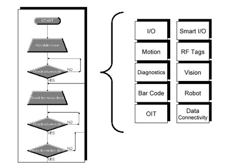
Interfaces to smart I/O can pull diagnostic information from sensors, actuators, or other intelligent devices, and can be as simple as adding a single block to the flow chart. Complex data handling, such as sorting algorithms which could take weeks to program in PLC ladder logic, becomes simple and straightforward with flow chart programming. Additionally, it can be programmed in hours.
Operator level diagnostics – The key to increasing uptime
Because most manufacturing equipment involves some form of mechanical operations -faults, jams, and failures are inevitable. One key to lowering the equipment downtime is to lower the overall MTTR (Mean Time to Repair) through immediate diagnose, repair and restart of a faulted piece of equipment. The faster a piece of equipment can be recovered, the lower its downtime and the higher its utilization capacity and resulting return on assets (ROA).
Operator level diagnostics can be difficult and expensive to design with PLC ladder logic. As the system changes, it is also difficult to keep the diagnostics up to date. Flow chart programming has diagnostic management tools available for engineers to rapidly design machine diagnostics. Diagnostics can be built directly into the control program to automatically diagnose equipment faults and provide the operator with repair, recovery, and restart methods through HTML-based graphical instructions. Machine diagnostics become as easy as 1, 2, 3:
1. Take digital pictures of the recovery process.
2. Create HTML pages linking digital pictures and operator recovery instructions into a logic fault recovery sequence using off-the-shelf tools such as Microsoft's PowerPoint.
3. Link the HTML file through a Diagnostic Wizard inside the flow chart.
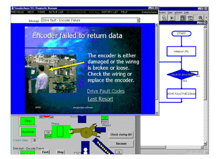
When an error occurs on the machine or during the process, the operator is immediately informed of the fault, and provided with graphical fault recovery tools to bring the machine on-line as quickly as possible. An example of a fault recovery screen is shown in Figure 3.
Crossing organizational boundaries to improve the process
Another driver behind the rapid adoption of PC-based control and flow chart programming is the capability to cross-organizational boundaries. Beyond the controls engineers and electricians, flow charts are also easily understood by IT managers, process engineers, mechanical engineers, and operators.
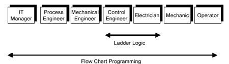
Where traditional PLC ladder logic is understood by the controls engineer and the electrician, the upstream process engineers and mechanical engineers may find it difficult to understand the cryptic "circuit diagram" programming. Downstream, the mechanical-skilled tradesmen may have difficulty understanding the operation by using ladder logic, and in most cases it is fairly impossible for the controls engineer or electrician to reconstruct a high level view of the actual machine operation through ladder logic.
Flow charts cross the traditional functional boundaries of a manufacturing organization because they have the ability to be easily understood by all. With the tools to easily access data locally and remotely over the network through the Microsoft DNA architecture, access to production data can now be easily handled by an organization's IT group.
A number of mechanical and process engineers are using flow chart programming tools to specify the system design and sequence of operations. Once the sequence of operations is defined, the flow chart outline of the process is turned over to the controls engineer to fill out the control logic details.
Flow chart programming also provides the capability for the mechanical and process engineers and skilled tradesmen to understand exactly how the machine or process is being controlled. A self-documenting set of flow charts can be as intuitive to read as a graphical trouble-shooting guide. Mechanical and electrical technicians are able to easily maintain and troubleshoot a failed machine by monitoring flow charts which are highlighted step-by- step as the machine executes.
Flow chart programming users also achieve the unexpected benefit of tools to continuously improve their process. Flow charts graphically document the automation process and make it easy to understand. This allows process and controls engineers to shift their focus from integrating multiple legacy controllers, multiple databases using complex programming tools, to focus on improvement of the manufacturing process and improvement of equipment throughput.
It's all about productivity
Simplifying the process, cutting design time, launch time and time to market, and reducing equipment downtime - all lead to higher profitability and a competitive advantage in the market place. Mainstream machine builders are recognizing the value and adopting PC-based control.
Consider these results:
- ABB Industrial Systems retrofitted a legacy control system for cigarette assembly machines with PC-based control and flow chart programming. They cut their system design time from 72 man-months of engineering time to 14 man-months, experienced an 80% savings in engineering design costs, cut their time to market from two years to seven months - a 66% reduction, and increased machine uptime by an additional 33%.
- Alvey Inc. reduced system design time by 50% on their PC-based gantry robot palletizer equipment, compared to a previous PLC design. With the new system they were able to incorporate a new feature - user-level diagnostics.
- Johnstone Pump abandoned a four months effort to design a system with traditional IEC-1131 based PLC tools, and instead redesigned the entire control system in four weeks using flow chart programming tools. At the same time, Johnstone Pump was able to develop a key differentiating feature with built-in diagnostics on all of their standard equipment.
Back to top
Conclusion
Automation can once again be used as a key competitive weapon in the rapidly changing manufacturing environment. Fortune 500 companies are leveraging next generation PC-based control tools with flow chart programming to get a higher level of productivity in their automation system design. By cutting their design costs and time to market and increasing communication across multiple disciplines, they have been able to develop higher levels of efficiencies which could not be achieved with their legacy control systems.
The capability to offer operator-level diagnostics and data connectivity with their equipment has enabled manufacturers to significantly differentiate their products, and gain a competitive advantage.
Back to top
About the author
Mike Klein, President and CEO of Steeplechase Software, Inc., is an industry-recognized speaker with many years of experience in controls, control networks, and industrial automation. Most recently, he has presented papers for National Manufacturing Week, Global Powertrain Congress, ISA, and ARC Advisory Group Annual Conference.
This article is provided courtesy of the ISA - the Instrumentation, Systems, and Automation Society.